

A lift plan can miss critical risks if it focuses on the lifting movement but overlooks the ground, route, load, crew communication or space the equipment needs. Common mistakes in lift planning include incomplete risk and contingency checks, unclear responsibilities, incorrect assumptions about load or reach, and equipment setup that does not account for its full footprint.
It’s easy to focus on choosing equipment and completing the task, but a workable plan must also prepare the crew for changing conditions and unexpected obstacles. This article covers practical checks for risk assessment, pre-lift communication, lift geometry, routes, loads and equipment setup. It also explains why planning safety zones, maintenance access and rescue arrangements early can prevent problems that a plan focused only on the lift itself might miss.
Key Takeaways
- Build risk and contingency checks around actual site conditions, including ground support, weather and the possibility that the plan may need to change.
- Use a pre-lift discussion to clarify the lift sequence, responsibilities, communication signals and how the crew will respond if conditions shift.
- Check how the load’s centre of gravity and pick points affect balance, rigging and the equipment’s capacity before committing to the lift.
- Assess the load and full travel route for obstructions, access constraints and safe positioning, not just the initial pick.
- Plan the equipment’s working footprint alongside maintenance access, safety zones and arrangements for dealing with an interruption.
1. Risk assessment and contingency planning
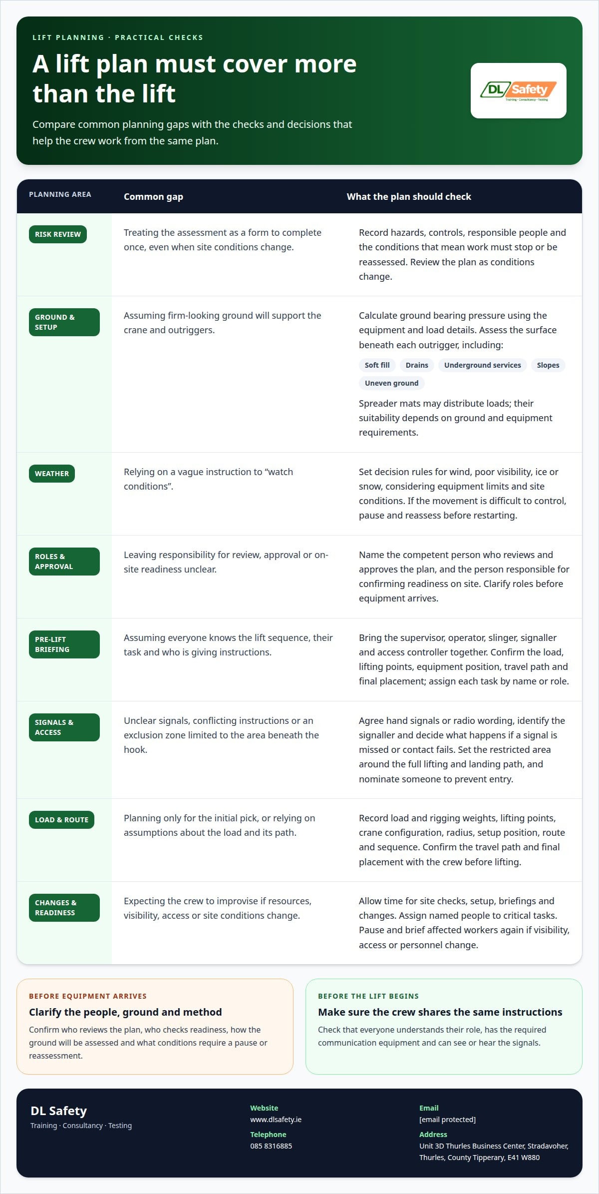
A useful risk assessment links the load, equipment, ground and crew to practical controls. One common mistake in lift planning is treating the assessment as a form to complete once, instead of a working plan to update when site conditions change. Rain, for example, can soften ground beneath an outrigger, while a delivery vehicle may block the planned crane position. Record the hazards, controls, responsible people and conditions that require work to stop or be reassessed.
There is no single weight threshold for classifying a lift as non-routine or complex. Unusual loads, restricted access, difficult ground or a departure from the normal method are all reasons for closer review. The plan should name the competent person who reviews and approves it, as well as the person responsible for confirming readiness on site. Clarify these roles before equipment arrives.
Crane stability depends on the combined effect of load weight, lifting radius, boom configuration, outrigger position and ground strength. Calculate ground bearing pressure using the equipment and load details, then assess whether the surface can support the reaction beneath each outrigger. Check for soft fill, drains, underground services, slopes and uneven ground. Spreader mats can distribute loads, but their suitability depends on the ground and equipment requirements. Never assume that firm-looking ground has enough capacity.
Weather planning needs clear decision rules, not a vague instruction to “watch conditions”. Set out how the operator will respond to wind, poor visibility, ice or snow, taking the equipment’s operating limits and site conditions into account. Wind can affect load control, while poor visibility can prevent clear signalling. If conditions make the planned movement difficult to control, pause the lift and reassess before restarting.
A complete lift plan records the load and rigging weights, lifting points, crane configuration, radius, ground assessment, setup position, route, sequence, crew roles and communication method. It also identifies hazards, controls, weather limits and contingency actions. Include enough detail for the operator and lifting crew to follow the same method, rather than relying on assumptions made during planning.
Set a realistic schedule. Allow time for site checks, equipment setup, briefings and changes, and consider the crew’s skills, availability, energy and capacity to focus. Assign a named person to each critical task, such as checking lifting gear or controlling access. If resources are short, resolve that before the lift rather than expecting the crew to improvise. Review the plan regularly, implement agreed changes and record lessons from completed work to improve future assessments.
2. Pre-lift meetings and communication protocols
A pre-lift meeting turns the written method into a sequence of shared actions. Bring together the lift supervisor, operator, slinger, signaller and anyone controlling access. Confirm the load, lifting points, equipment position, travel path and final placement. Assign each task by name or role so no critical check depends on an assumption. Use the meeting to identify differences between the plan and actual site conditions before the lift begins.
Agree on one clear method for giving instructions. The operator should be able to identify the signaller, and the crew should use agreed hand signals or radio wording. Specify what to do if a signal is missed, radio contact fails or the load stops moving as expected. For example, agree that anyone can call “stop” and that movement resumes only once the signal is understood and the issue is resolved. A clear briefing helps prevent conflicting instructions.
Poor communication can leave workers inside the danger area, prompt unexpected crane movement or allow a load to swing without timely control. An inadequate exclusion zone exposes people to a suspended or shifting load, which can strike structures, equipment or workers. Set the restricted area around the full lifting and landing path, not just beneath the hook, and nominate someone to prevent entry.
Coordination matters when work activities overlap. If a delivery driver, site supervisor or another crew can affect access, include their activity in the sequence and clarify who controls the area. Ask the team to identify pinch points, blind spots and competing movements. Record sequence changes, who authorised them and how revised instructions reached everyone involved. A brief repeat-back from the operator and signaller can confirm that key directions were understood.
If a lift may affect people beyond the work crew, plan communication before setting up the equipment. Identify nearby homes, businesses, road users or site teams that could experience noise, restricted access or temporary disruption. Explain the expected work area and timing through the appropriate project channel, and assign a named contact to receive and relay concerns. Log community objections and pass them to the project lead, who can assess whether access, timing or the work method needs adjustment. A notice alone may not resolve a concern.
End the meeting by confirming the crew’s readiness and ability to carry out the work. Check that everyone understands their role, has the required communication equipment and can see or hear the signals. If visibility, access or personnel change, pause and brief the affected team again. Keep the agreed instructions available at the work area so returning crew members receive the same information instead of relying on a hurried handover.
3. Centre of gravity and pick-point geometry
A load can weigh less than the equipment’s rated capacity and still become unstable if its centre of gravity is misjudged. This is the point around which the load’s weight acts. If the hook is positioned away from it, the load may tilt, rotate or shift as tension comes onto the slings. For example, a steel frame with a heavy motor fixed at one end will not balance like a uniform beam.
Start with the load’s drawings, lifting instructions and physical configuration. Identify heavy components, empty spaces and anything that could move internally, such as liquid in a tank. Compare the documented design with the actual item, as fitted accessories or removed parts can change its balance. If you cannot establish the centre of gravity reliably, do not treat an estimated position as a confirmed lifting point.
Next, map the proposed pick points against the centre of gravity. The points must suit the load’s structure and intended orientation, not just provide convenient places to attach slings. Pick points that are too close together can increase the risk of rotation; asymmetrical placement can create unequal sling loading. A spreader beam may help keep sling forces more vertical, but its selection and configuration must match the lift design.
Geometry also covers sling length, attachment direction and clearance. Check that each sling can reach its point without bearing against sharp edges, twisting, snagging or contacting fragile parts. A sling at a shallower angle experiences greater tension than a vertical sling carrying the same load. Account for that effect in the rigging configuration and confirm each item’s rated capacity for its intended use.
Before the main movement, the lifting team should take up slack gradually and observe the load’s response from a safe position. If one side rises first, the load twists or a sling shifts, stop and lower the load in a controlled manner. Reassess the centre of gravity, pick-point spacing and sling lengths before changing the arrangement. Never try to correct an imbalance by placing workers near a suspended load or pulling it by hand.
Failing to update the plan after a change can invalidate the original geometry checks. Recalculate if the load’s contents, attachments, orientation or lifting points change. Record the revised arrangement and brief the operator and slinger before proceeding. Removing a machine guard or adding a lifting beam, for example, changes the assembly being handled, so the plan must reflect the new configuration.
Clear drawings or a simple annotated sketch can show the centre of gravity, pick points, sling paths and intended orientation. These details give the crew a shared reference and support learning after the lift. Compare the planned balance with the load’s observed response, record any adjustments and apply those lessons to future lifts.
4. Checking the route and load before lifting
A route that looks clear on a drawing may be blocked by a delivery, stored materials or temporary works. Walk the planned path from the pick-up point to the landing position, including the space needed to turn or slew. Check overhead beams, doorways, cables, floor openings, slopes and pedestrian access. Involve people who know the work area, as site changes may not appear on a desk plan.
Before lifting, confirm the load’s actual weight, dimensions, shape and condition against available records and markings. Include attached items and rigging hardware in the total lifted weight. Check whether the load could shift, snag or catch on a doorway during travel. Plan where it will be gripped and set down, leaving enough room to release slings without putting hands beneath it.
A mobile crane plan must account for the crane’s position, working radius, boom configuration, travel route and ground support. A tower crane plan must address the lifting area, load path, height and interaction with surrounding structures. A forklift plan centres on the load, attachment, capacity at the operating position, travel surface and visibility. Each method needs equipment-specific checks, not a copied plan.
For work in Ireland, plan lifting operations around applicable workplace safety and work-equipment requirements, including suitable equipment, inspection arrangements and competent operation. EU requirements inform the framework, while relevant Irish obligations and equipment instructions guide site arrangements. The plan should identify who checks the equipment, which inspection records apply and how the operator’s competence matches the machine and task.
At the work area, compare the load and route with the approved method before lifting. Confirm the identification and condition of lifting accessories, the hook and attachment points, the crane or forklift configuration, and the landing area. Check that the route remains clear and barriers protect people from the moving load. If the equipment, load or site layout differs from the plan, stop and revise the method before continuing.
The briefing should include the operator, slinger or load handler, signaller and people controlling access. Review the sequence, travel path, landing position and agreed stop signal. For example, if a reversing vehicle enters the route, the crew should know who pauses the lift and who clears the obstruction. Clear roles and shared understanding help prevent unsafe improvisation and delays that can disrupt the work.
These checks matter because a route change can affect both equipment position and load control. Record the actual route, restricted areas and the person responsible for keeping them clear. Repeat the check after a delivery, change in weather or shift handover, when the site may no longer match the original plan.
5. Equipment setup footprint and contingency planning
A lift’s footprint includes more than the machine’s parked position. Mark the space needed for outriggers, counterweight swing, load movement, access routes and barriers on the site layout. A crane may fit between two buildings but still block an emergency route once its outriggers are deployed. Compare its full working envelope with nearby structures, stored materials, vehicle movements and pedestrian routes.
Ground conditions and buried services can limit equipment positioning. Identify drains, ducts, chambers and service routes before placing support legs, then assess the surface beneath the proposed setup. A mat or spreader can distribute pressure, but it does not make every location suitable. Record the chosen position, support arrangement and any exclusion area so the crew can see how the setup fits the site.
Plan for the work around the lift as well. Leave practical access for inspection, maintenance and equipment removal instead of boxing the machine in with materials or temporary structures. If a component needs servicing during a longer operation, restricted access can extend downtime and create pressure to work in an unsuitable position. Include rescue access and a route for bringing assistance into the work area.
Contingency planning should specify what conditions trigger a pause and who decides what happens next. Triggers may include changed ground conditions, an obstruction in the work area, loss of access, equipment failure or weather that affects the operation. State where the load will be made safe if work stops, who controls the area and how the crew will receive a revised plan. Do not assume the original position remains workable after conditions change.
Match responsibilities to people’s skills. The person overseeing setup needs to recognise when the actual arrangement differs from the planned footprint. The operator, lifting crew and site contact should understand the stop-work process and who can authorise a change. Keep the equipment instructions and agreed setup details available at the work area. If the planned position cannot be achieved, stop and reassess rather than forcing the equipment into a smaller space.
Review the layout before work starts and after significant site changes, such as new storage, a diverted delivery route or temporary works. Check that barriers remain effective, access stays clear, and maintenance and rescue routes remain usable. Record changes and brief affected people before restarting. This makes the footprint a practical control, not just a mark on a drawing, and gives the team a clear way to adapt safely.
Where equipment selection or condition forms part of the setup decision, explore lifting equipment suited to the work.
DL Safety: Lift Plans
DL Safety prepares Lift Plans that bring together the load, equipment, site conditions and crew roles in a coordinated working method. This is a practical step when a lift involves challenging access, uncertain ground conditions, complex load geometry or several teams working in the same area. A clear plan helps settle key decisions before work starts, so the crew understands the sequence, controls and arrangements for managing change.
Share the lift details and site requirements so the plan can address the task and its constraints. DL Safety also offers Monthly Safety Support Packages, GA1 Testing and Accident Investigation where these meet wider workplace safety needs. Contact DL Safety at info@dlsafety.ie or call 085 8316885. The address is Unit 3D Thurles Business Center, Stradavoher, Thurles, County Tipperary, E41 W880.
Make the next lift easier to plan
A lift plan should remain useful beyond the day it is written. Treat each operation as an opportunity to improve how your team records site changes, shares decisions and applies lessons to future work. This helps planning reflect how work actually happens, rather than relying on assumptions carried over from an earlier job.
Common mistakes in lift planning are easier to address when planning is part of the work process, not a last-minute paperwork exercise. Give the crew time to raise concerns, record changes and review the plan properly before the next lift. A consistent approach supports clear decisions without adding unnecessary complexity.
If you’re preparing a lift and would value support shaping the plan around your operation, start a conversation with DL Safety. A considered next step can help your team approach the work with greater clarity and confidence.
Frequently Asked Questions
What are the most common lift planning mistakes?
Common mistakes include relying on estimated load details, overlooking changes made after planning and leaving key decisions unclear between crew members. A replacement component, for example, may have been added to a machine after its weight was recorded. Compare the planned configuration with the item presented for lifting and pause if they differ. The plan should also explain how to stop the work safely if the original sequence cannot continue.
How do you determine crane capacity and load chart limits for a lift?
Use the crane’s load chart for its actual configuration and lifting position. Check that the chart matches the boom length, operating radius and counterweight arrangement, then compare its capacity with the full suspended load. Include slings, shackles, spreader bars and other rigging hardware in the total. Moving the crane farther from the load, for instance, changes the radius, so a capacity figure for a closer position may not apply.
How should lifting points and the load’s centre of gravity be assessed?
Use the load’s design information and manufacturer-identified lifting points to establish a suitable arrangement. Consider whether contents or attachments could shift the balance, as with a machine that has a heavier drive unit at one end. The intended orientation matters too: a load that hangs level in one position may tilt when turned. Check that the rigging will control the load throughout the lift, not only when tension is first applied.
How do you calculate the weight of a load and lifting accessories?
Include the load’s weight and the weight of all rigging accessories, such as slings, shackles and spreader bars, in the crane load calculation.
